What is the creepage distance of an insulator?
Worried about insulator flashovers causing power outages? Contamination buildup can create conductive paths. Proper creepage distance prevents this costly problem for your power systems.
Creepage distance is the shortest path along an insulator's surface between conductive parts. It's crucial for preventing electrical breakdown caused by surface contamination like dust, salt, or moisture collecting on the insulator.
Understanding creepage distance is fundamental for selecting the right insulator for any project. Getting this wrong can lead to failures down the line. But what does this term really mean in practical terms for engineers and grid operators? Let's explore this further to ensure your power systems remain safe and reliable, avoiding unnecessary risks and costs. We need to make sure we select components that last.
What is meant by creepage distance?
Confused by technical jargon like 'creepage distance' when specifying equipment? Misunderstanding this term can lead to incorrect insulator choices for your projects. We want to make it simple and clear for everyone involved.
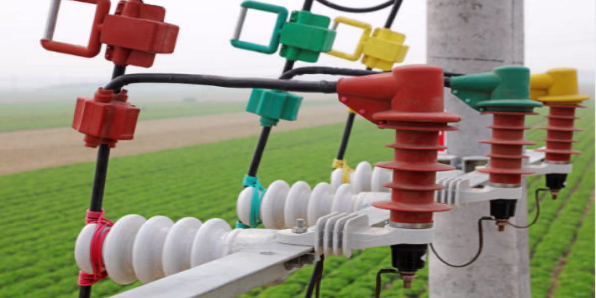
Creepage distance simply means the shortest distance electricity must travel along the surface of an insulator between two conductive points (like the metal cap and pin). Think of it as the winding path over and under the insulator sheds, not a straight line.
!
It's essential to distinguish creepage distance from clearance distance. Clearance is the shortest distance through the air between two conductive parts. Creepage distance is always measured along the surface. Imagine a winding mountain road versus a straight tunnel through the mountain – the road represents the creepage path, and the tunnel represents the clearance. The creepage path follows every contour of the insulator, including the top and bottom surfaces of the sheds or skirts. These sheds are designed specifically to make this surface path as long as possible within a given insulator height. The shape, number, and spacing of these sheds directly influence the total creepage distance. At Yuanneng Power, we carefully design the profiles of our composite insulators to maximize this distance, ensuring better performance, especially in polluted areas. This design consideration applies to all types of insulators we work with, including those used in our fuses and arresters.
Creepage vs. Clearance Distance
It's easy to mix these two up, but they serve different purposes.
- Creepage Distance: Measured along the insulator surface. Protects against tracking and flashover due to surface contamination.
- Clearance Distance: Measured through the air (shortest straight line). Protects against flashover directly through the air, mainly influenced by voltage levels and atmospheric conditions.
Both are important, but creepage distance is particularly critical when surface pollution is a concern.The Role of Insulator Shape
The complex shapes of high-voltage insulators, especially the sheds, aren't just for looks. Their primary function is to increase the creepage distance. By forcing any potential leakage current to travel a longer, more complex path over and under these sheds, the insulator's resistance to surface flashover is significantly increased. We optimize these shapes based on the intended application and environmental conditions.
Why is creepage distance important in insulators?
Are you facing unexpected insulator failures in your network? Environmental pollution might be creating invisible conductive tracks on insulator surfaces. Having adequate creepage distance is your first line of defense against these flashovers.
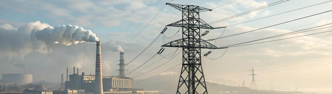
Creepage distance is vital because it prevents flashovers caused by surface contamination. Pollutants like dust, salt spray, or industrial chemicals, combined with moisture (like dew or fog), can create a conductive layer, letting electricity 'creep' across the insulator. A longer path resists this breakdown.
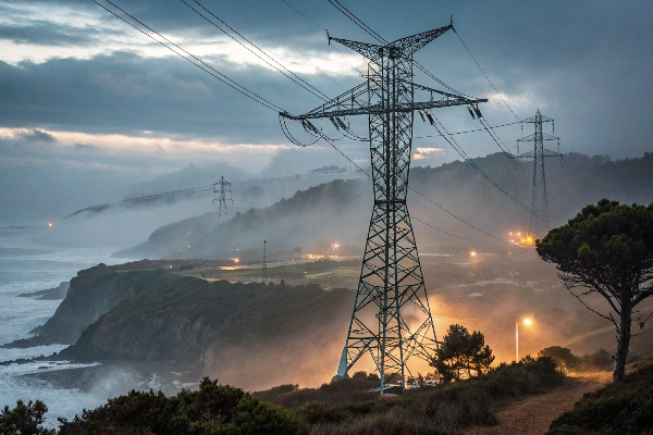
The danger starts when contamination builds up on an insulator's surface. When this layer gets damp, it becomes slightly conductive, allowing a small leakage current to flow. This current generates heat, which can dry out parts of the contaminated layer, forming 'dry bands'. Electrical arcs can then form across these dry bands. If these small arcs join together and bridge the entire distance between the energized cap and the grounded pin, a full flashover occurs, leading to a power outage. A longer creepage distance makes it harder for these arcs to bridge the entire insulator. It provides more surface area, meaning the contamination layer is often thinner and less conductive overall. Different environments pose different risks. Coastal areas have salt spray, industrial zones have chemical pollutants, and desert regions have dust. Each requires a specific minimum creepage distance for reliable operation. This is why, drawing on our global project experience from Southeast Asia to Africa, we always emphasize assessing the site's pollution level. Our composite insulators also feature hydrophobic surfaces, which resist wetting and help maintain high surface resistance, but the fundamental requirement for sufficient creepage distance always remains.
Contamination and Flashover Risk
Pollution is the enemy of insulator performance. The type and amount of contamination directly impact the required creepage distance. Even seemingly clean environments can have seasonal pollution (like agricultural dust) that needs consideration. Regular washing can help, but designing with the correct creepage distance from the start is more effective and economical.
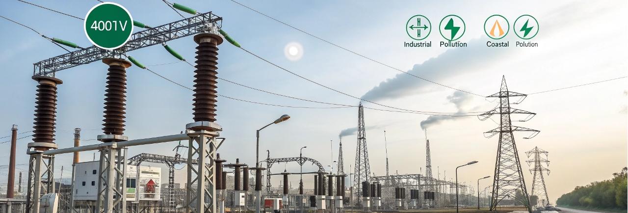
Pollution Levels and Standards (IEC 60815)
To standardize selection, international standards like IEC 60815 classify pollution levels. This helps utilities and EPC contractors specify the right insulators.
| Pollution Level | Description | Typical Environment | Recommended Minimum Specific Creepage (mm/kV) |
|---|---|---|---|
| I - Light | Low non-soluble deposits | Clean areas, deserts | 16 |
| II - Medium | Moderate conductive deposit | Areas with some industry | 20 |
| III - Heavy | High conductive deposit | Industrial areas, near coast | 25 |
| IV - Very Heavy | Very high conductive deposit | Heavy industry, heavy coast | 31 (or more) |
Note: These are minimums; specific project requirements might demand higher values.
How do you calculate creepage distance for insulators?
Are you unsure how to specify the right insulator creepage for your next project? Selecting the wrong value risks system failure or unnecessary overspending on oversized insulators. Luckily, learning the standard calculation method is straightforward.
Calculating the required minimum creepage distance involves multiplying the system's highest line-to-line voltage (kV) by a specific creepage factor (mm/kV). This factor is chosen based on the expected pollution level of the installation site.
The calculation itself is simple, but choosing the inputs correctly is key. The formula is:
Total Creepage Distance (mm) = System Voltage (kV) × Specific Creepage Distance (mm/kV)
First, you need the system voltage. This is typically the highest nominal line-to-line voltage the insulator will experience during operation. For example, on a 132 kV nominal system, the highest operating voltage might be slightly higher, say 145 kV, and this higher value should usually be used for conservatism. Next, you need the specific creepage distance factor, sometimes called USCD (Unified Specific Creepage Distance). This value directly relates to the pollution severity at the installation site. International standards, mainly IEC 60815, provide guidance by classifying pollution levels from I (Light) to IV (Very Heavy) and recommending corresponding minimum specific creepage factors. For instance, a Level III (Heavy) pollution environment typically requires at least 25 mm/kV. So, for our 145 kV system in a Level III area, the minimum required creepage would be 145 kV * 25 mm/kV = 3625 mm. Accurately assessing the site's pollution level is critical. This might involve site surveys, historical data analysis, or consulting local expertise. At Yuanneng Power, we often assist our clients, including EPC contractors and utility engineers, in making this assessment and selecting the most appropriate specific creepage factor based on the project location and applicable standards.
The Calculation Formula Explained
The formula provides a baseline requirement. It ensures the insulator surface path is long enough to withstand the expected voltage stress under anticipated pollution conditions. Remember, this calculation gives the minimum required distance; sometimes, selecting an insulator with a slightly longer creepage distance provides an extra safety margin, especially if future environmental changes are possible.
Choosing the Right Specific Creepage Factor
Selecting the specific creepage factor (mm/kV) is the most critical part of the calculation. Overestimating the pollution leads to buying more expensive insulators than needed. Underestimating it significantly increases the risk of flashovers and outages.
| IEC 60815 Pollution Level | Minimum Specific Creepage (mm/kV) | Example Environments |
|---|---|---|
| I - Light | 16 | Clean rural areas, areas with very low industry |
| II - Medium | 20 | Areas with light industry, agriculture, near highways |
| III - Heavy | 25 | Industrial zones, areas near moderate coastline |
| IV - Very Heavy | 31+ | Heavy industrial complexes, direct coastal exposure |
Always refer to the latest standards and consider local experience when choosing this factor. Sometimes, factors like altitude or specific types of conductive pollutants might require adjustments even beyond these standard values.
What is the creepage path of an insulator?
Visualizing the exact creepage path on a complex insulator shape seems tricky sometimes. Not understanding the actual route electricity tries to take along the surface can lead to poor design interpretations or underestimating its importance. Let's trace this path together.
The creepage path is the actual route along the insulator's surface that leakage current would follow between the energized end fitting (cap) and the grounded end fitting (pin or base). It meticulously follows all the contours, including going over and under the sheds.
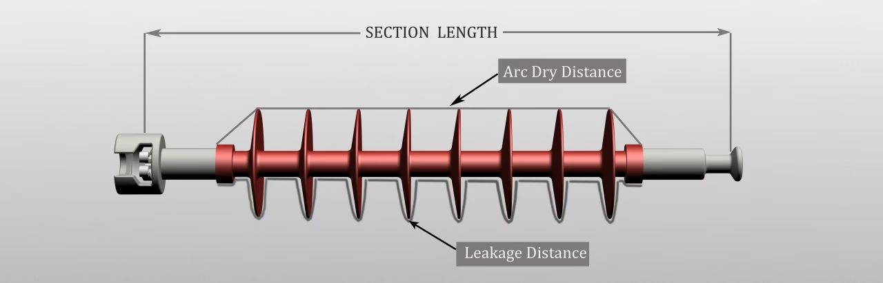 )
)
Imagine stretching a measuring tape tightly along the insulator's profile, following every curve and indentation from the metal cap down to the metal pin – that’s the creepage path. It’s specifically designed to be much longer than the simple height of the insulator. The sheds, or skirts, are the key features that achieve this. They force the path to zigzag up and down, significantly increasing its length compared to a smooth cylinder of the same height. This extended path is crucial for performance under contaminated conditions. It must not be confused with the arcing distance (or clearance distance), which is the shortest straight-line path through the air between the end fittings. The creepage path is always longer than the arcing distance. Different shed profiles are used to optimize the creepage path and performance characteristics. For example, aerodynamic profiles can encourage self-cleaning by wind and rain, while deeper profiles might offer more protection in areas with heavy, sticky pollution. At Yuanneng Power, we utilize CAD (Computer-Aided Design) tools extensively during the development of our composite insulators. This allows us to precisely model and optimize the shed shapes to maximize the creepage path while also considering factors like water shedding and resistance to bird nesting, contributing to overall grid reliability. Finally, the designed creepage distance is verified through physical measurement on prototypes and production units according to standards like IEC 60383 or IEC 61109.
Following the Surface Contours
The definition is strict: it's the shortest path along the surface. This means the measurement must hug the insulator body, going over the tops of sheds and dipping down into the undersides before climbing up the next one. This meticulous tracing ensures the true distance a leakage current would have to travel is captured.
Shed Design and Its Impact on the Path
The number, diameter, spacing, and angle of the sheds are all critical design parameters.
- More sheds: Generally increase creepage distance for a given length.
- Larger diameter sheds: Increase the path length significantly.
- Optimized spacing and angle: Prevent bridging by water streams during rain and allow for better self-cleaning.
Our engineering team balances these factors to create insulators effective for specific voltage levels and pollution environments.Creepage Path vs. Arcing Distance
It’s worth repeating the difference:
- Creepage Path: Along the surface, over/under sheds. Relevant for pollution flashover.
- Arcing Distance: Straight line through the air. Relevant for air insulation breakdown (lightning/switching surges).
An insulator must satisfy requirements for both distances to function safely.
Conclusion
Understanding creepage distance is key to selecting reliable insulators. It's the surface path length designed to prevent flashovers from pollution. Remember to calculate it using system voltage and the site-specific pollution factor. We at Yuanneng Power are here to help you choose the right products.