Fuse Cutouts: How They Provide Critical Overcurrent Protection in Power Distribution?
A sudden power surge can destroy expensive equipment. Fuse cutouts act as silent guardians, instantly cutting off dangerous currents before damage occurs.
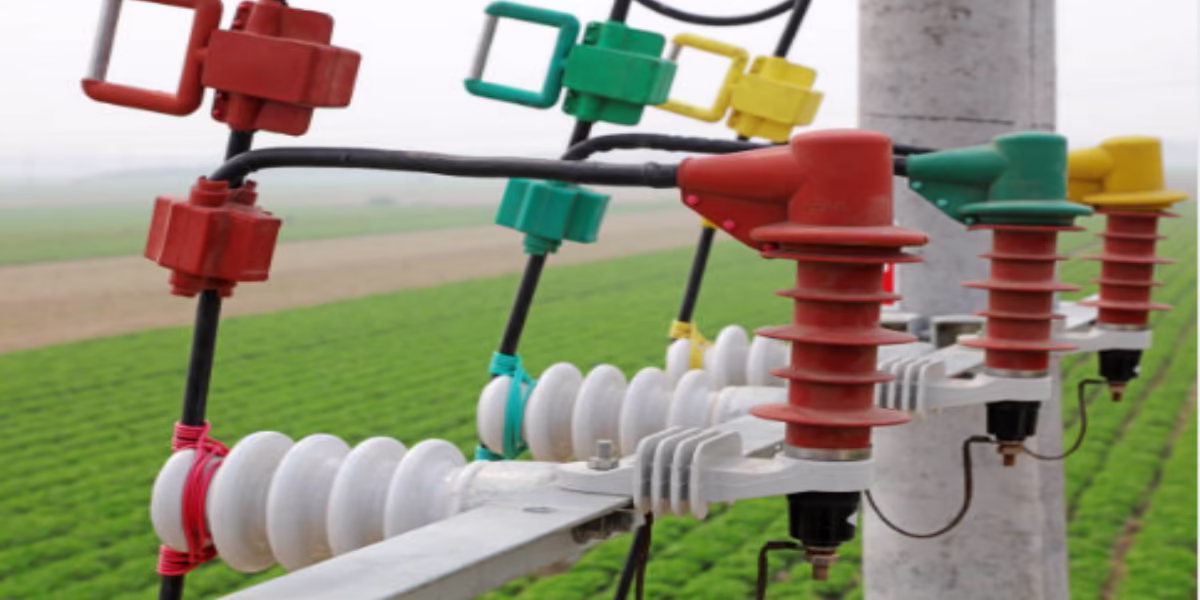
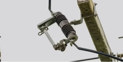
Fuse cutouts are safety devices that interrupt excessive current flow in power lines. They contain a fuse link that melts during overloads, physically disconnecting the circuit to protect transformers and other equipment.

Most people never notice fuse cutouts until they fail. Understanding how they work could prevent costly power outages.
How do power line cutouts work?
Imagine an electrical system with no safety switches. Fuse cutouts provide the emergency stop button for power lines.
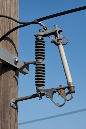
These devices combine a fuse holder with a mechanical release mechanism. When current exceeds safe limits, the fuse melts and gravity pulls the fuse tube downward, visibly indicating the fault.
The Operating Sequence
-
Normal Operation
- Current flows through the fusible link
- The fuse tube remains in closed position
- No visible change in the device
-
Overcurrent Event
- Excessive heat melts the fuse element
- Internal pressure builds up in the fuse tube
- The mechanical latch releases
-
Fault Isolation
- The fuse tube drops open (hence "drop-out" design)
- Creates visible air gap in the circuit
- Maintenance crews easily spot the tripped fuse
| Key Components: | Part | Function | Material |
|---|---|---|---|
| Fuse Tube | Houses the fuse link | Weather-resistant polymer | |
| Fusible Element | Melts during overload | Silver or tin-coated copper | |
| Holder | Provides mechanical support | Galvanized steel or aluminum |
What are the different types of fuse cutouts?
Not all electrical faults are equal. Fuse cutouts come in specialized versions for different protection needs.
Common types include open-link, enclosed, and solid-material cutouts. Each design offers distinct advantages for voltage levels, environments, and fault current characteristics.
Type Comparison Table
| Type | Best For | Advantages | Limitations |
|---|---|---|---|
| Open-Link | Distribution lines (15-38kV) | Easy visual inspection | Exposed to weather |
| Enclosed | Urban/substation use | Better arc control | Harder to inspect |
| Solid-Material | High fault currents | No expulsion gases | Higher replacement cost |
Selection Factors:
- Altitude: Thin-air areas need special pressure considerations
- Pollution: Coastal areas require corrosion-resistant materials
- Temperature: Arctic versions use low-temperature alloys
Why are Fuse Cutouts Essential in Distribution Systems?
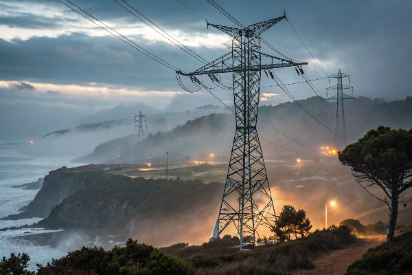
Power grids without fuse protection would fail daily. These devices prevent small faults from becoming catastrophic failures.
They protect transformers from damage, isolate faulted sections quickly, and provide visible fault indicators - all without needing external power sources.
Protection Benefits Breakdown
-
Equipment Safety
- Prevent transformer burnout
- Stop cable overheating
- Reduce switchgear damage
-
System Reliability
- Localize outages to smallest area
- Allow faster fault finding
- Enable targeted repairs
-
Economic Advantages
- Cheaper than circuit breakers
- Faster than relay-based systems
- Lower maintenance requirements
Real-World Example:
A 2019 grid study showed distribution networks with proper fuse cutouts experienced:
- 72% fewer transformer replacements
- 58% shorter outage durations
- 34% lower maintenance costs
How do you size a cutout fuse?
Wrong fuse sizing causes either nuisance trips or dangerous protection gaps. Proper selection follows clear engineering rules.
Fuse rating depends on load current, fault levels, and protected equipment specs. Standard practice uses 125-150% of normal load current for overhead lines.
Sizing Methodology
Step 1: Determine Load Characteristics
- Measure normal operating current (Iₙ)
- Identify maximum continuous load
- Note ambient temperature conditions
Step 2: Analyze Fault Conditions
- Calculate available short-circuit current
- Check clearing time requirements
- Consider upstream protection coordination
Step 3: Apply Correction Factors
| Condition | Multiplier |
|---|---|
| High Ambient Temp | ×0.85 |
| Enclosed Space | ×0.90 |
| Frequent Load Cycles | ×0.80 |
| Standard Ratings Table: | System Voltage (kV) | Common Ratings (A) |
|---|---|---|
| 15 | 6-200 | |
| 25 | 10-100 | |
| 38 | 20-150 |
How to calculate drop-out fuse rating?
Fuse calculations seem complex but follow logical steps. Field engineers use simplified methods for quick decisions.
The basic formula is: Fuse Rating = (Transformer VA) / (√3 × Voltage). Always round up to nearest standard size after calculations.
[image placeholder]
Calculation Process Example
Case Study: Protecting a 500kVA, 11kV/400V distribution transformer
-
Full Load Current
I = 500,000VA / (√3 × 11,000V) = 26.24A -
Fuse Selection
- Apply 150% safety margin: 26.24 × 1.5 = 39.36A
- Next standard size: 40A
-
Verification Checks
- Withstand 20x current for 0.1s
- Clear 3x current within 300s
- Coordinate with LV fuses
Common Mistakes:
- Ignoring cold load pickup currents
- Overlooking fault current limitations
- Forgetting altitude derating
Conclusion
Fuse cutouts provide vital protection through simple but reliable designs. Proper selection and maintenance ensure continuous power supply safety.